Published: by
OpAmp differential amplifier gain: Single-Ended Inputs vs. Double-Ended Input
The difference makes a difference …
I’ll show that the gain factor of an OpAmp differential amplifier will be different between single-ended operation and double-ended operation.
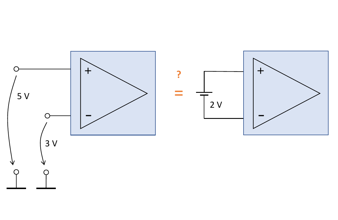
Single-ended operation is characterized by two input voltages, each referenced to ground (on the left side of the image above). In conrast, double-ended operation is characterized by one ‘floating’ input voltage, i.e. without reference to the ground potential (on the right side of the image above).
Note: The battery symbol has been used just to illustrate that the voltage source is potential-free and does not mean to be necessarily a battery component (it may be a sensor as well, for example).
Differential amplifier driven by single-ended inputs
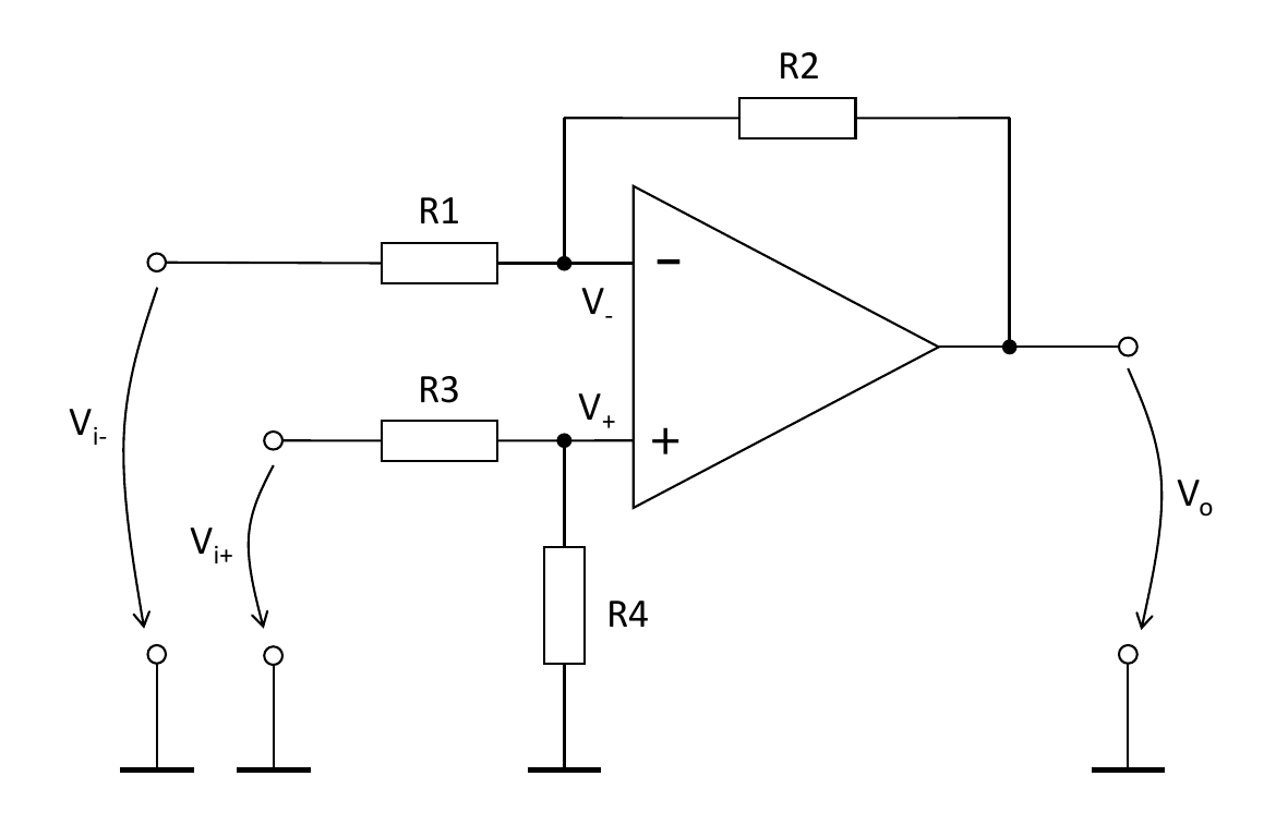
The feedback-controlled steady-state will be reached as soon as the ground-referenced input voltages equal each other:
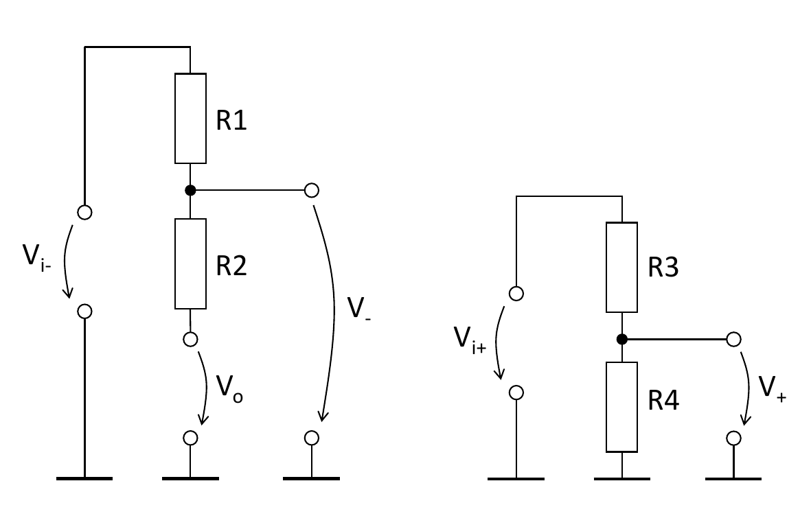
\[V_+ = V_-\]Here, \(V_+\) and \(V_-\) drop along different current pathes, driven by \(V_{i_+}\) and \(V_{i_-}\), respectively, see Fig. 2.
Applying voltage divider rules, we get:
\[\begin{align} V_{i_+} \frac{R_4}{R_3 + R_4} &= V_{i_-} \: + \: (V_o - V_{i_-}) \frac{R_1}{R_1 + R_2} \nonumber \\ V_{i_+} \frac{R_4}{R_3 + R_4} &= V_{i_-} \left(1 - \frac{R_1}{R_1 + R_2}\right) \: + \: V_o \frac{R_1}{R_1 + R_2} \nonumber \\ V_o \frac{R_1}{R_1 + R_2} &= V_{i_+} \frac{R_4}{R_3 + R_4} \: - \: V_{i_-} \left(1 - \frac{R_1}{R_1 + R_2}\right) \nonumber \\ V_o &= V_{i_+} \frac{R_1 + R_2}{R_3 + R_4} \frac{R_4}{R_1} \: - \: V_{i_-} \left(\frac{R_1 + R_2}{R_1} - 1\right) \nonumber \\ V_o &= V_{i_+} \left( \frac{R_1 + R_2}{R_3 + R_4} \frac{R_4}{R_1} \right) \: - \: V_{i_-} \left(\frac{R_2}{R_1}\right) \label{Eq:DiffAmp_SingleEnded} \end{align}\]With \(R_1 = R_2 = R_3 = R_4\) (i.e. unity gain) we get the net difference between the two gound-referenced input voltages:
\begin{equation} V_o = V_{i_+} \; - \; V_{i_-} \end{equation}
Differential amplifier driven by double-ended input
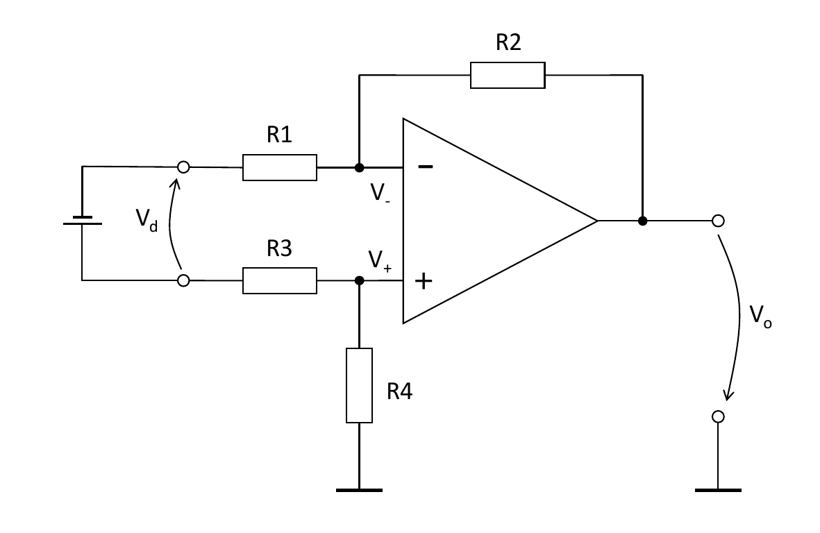
Again, the feedback-controlled steady-state will be reached as soon as the ground-referenced input voltages equal each other: \begin{equation}\label{Eq:DiffAmp_Base} V_+ = V_- \end{equation}
Perhaps you might expect that double-ended operation is equivalent to single-ended operation, given \(V_d = V_{i_+} - V_{i_-}\). However, this is not the case.
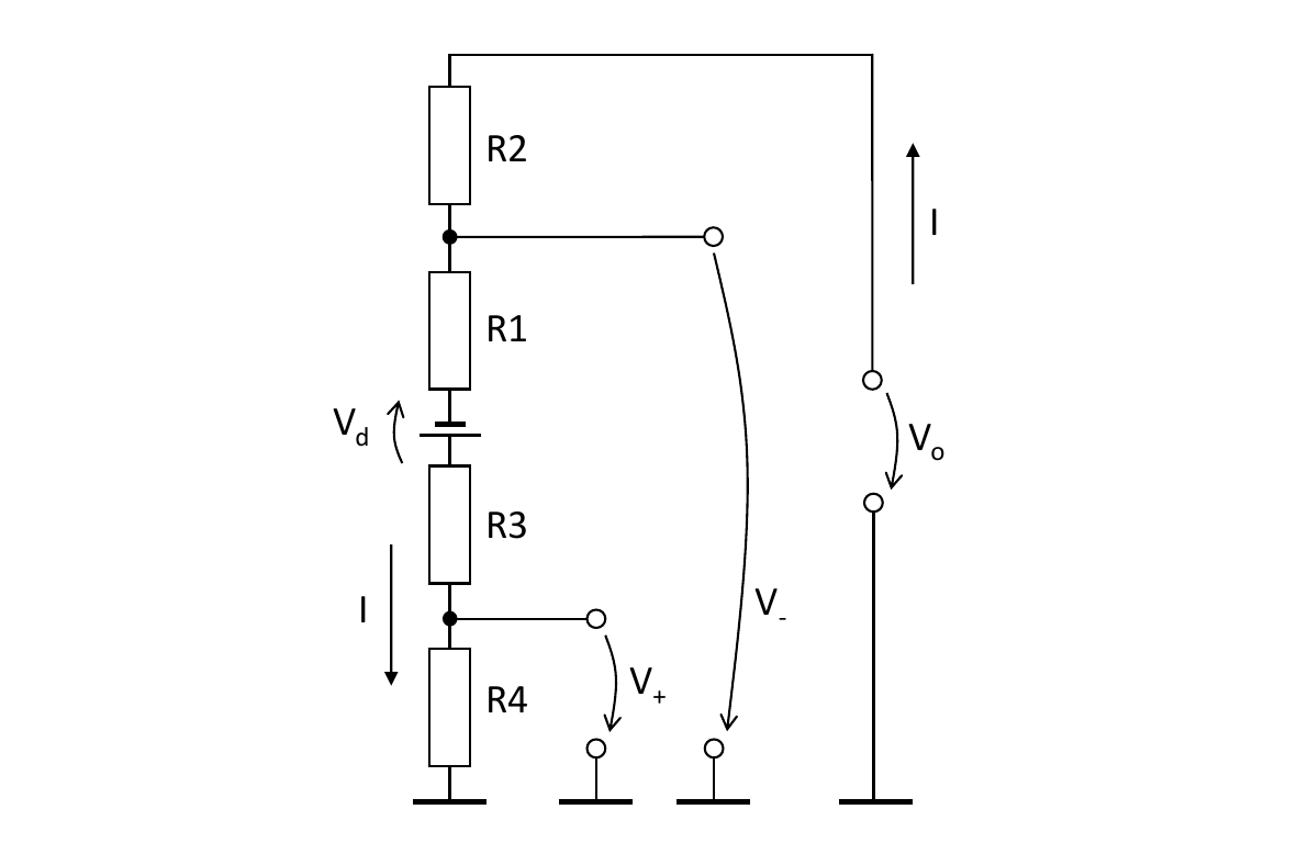
The crucial difference to single-ended operation is that for double-ended operation \(V_+\) and \(V_-\) are not created by means of separate current pathes but rather by a common mesh current back to the floating voltage source \(V_d\), see Fig. 4. This common mesh current is:
\begin{equation}\label{Eq:SingleEndedMeshCurrent} I = \frac{V_o + V_d}{R_1 + R_2 + R_3 + R_4} \end{equation}
From Fig. 4 we get:
\[\begin{align*} V_+ &= I \cdot R_4\\ V_- &= I \: (R_1 + R_3 + R_4) \: - \: V_d \end{align*}\]Therefore, Eq. \ref{Eq:DiffAmp_Base} becomes:
\[\begin{equation*} V_d = I \: (R_1 + R_3) \end{equation*}\]Furthermore, with Eq. \ref{Eq:SingleEndedMeshCurrent} we get:
\[\begin{equation*} V_d = \frac{V_o + V_d}{R_1 + R_2 + R_3 + R_4} \: (R_1 + R_3) \end{equation*}\]Rearranging to \(V_o\) yields:
\[\begin{align} V_o &= V_d \: \left(\frac{R_1 + R_2 + R_3 + R_4}{R_1 + R_3} \: - \: 1\right) \nonumber \\ V_o &= V_d \: \frac{R_1 + R_2 + R_3 + R_4 - R_1 - R_3}{R_1 + R_3} \nonumber \\ V_o &= V_d \: \frac{R_2 + R_4}{R_1 + R_3} \label{Eq:DiffAmp_DoubleEnded} \end{align}\]Mentally replacing \(V_d\) by \(V_{i_+} - V_{i_-}\) in Eq. \ref{Eq:DiffAmp_DoubleEnded} we see that the result would not equal Eq. \ref{Eq:DiffAmp_SingleEnded}.
One exeption holds for \(R_1 = R_2 = R_3 = R_4\).
It should be noticed that the implementation of the OpAmp differential amplifier as an instrumentation amplifier won’t be able to operate in a double-ended manner since their built-in voltage follower at the inputs \(V_{i_+}\) and \(V_{i_-}\) prevent the mesh current mentioned in Fig. 4 to flow.